
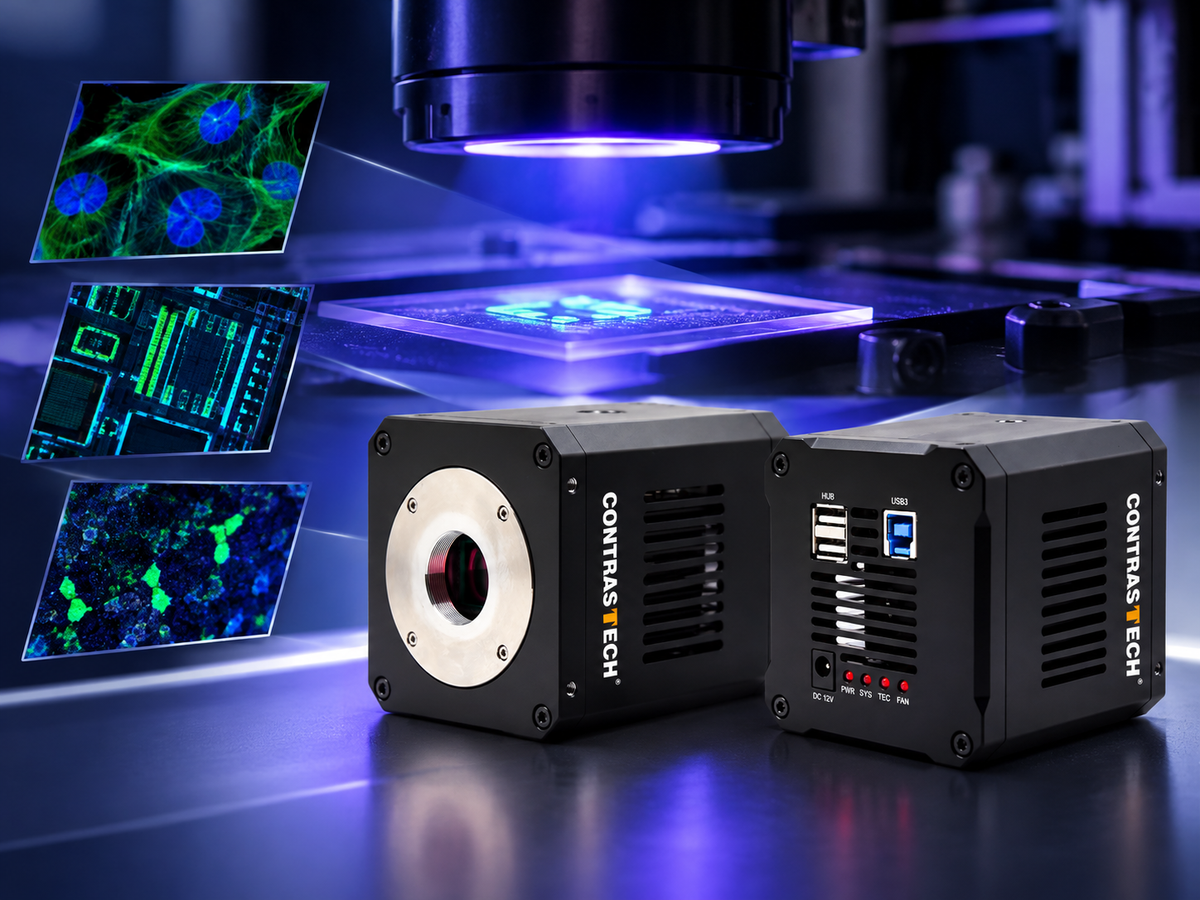
Fluorescence imaging enables researchers and engineers to visualize biological structures, chemical compounds, and materials that may be difficult to distinguish under conventional illumination. With the right excitation source, optical filters, and imaging detector, fluorescence signals can reveal information about a sample's composition, distribution, and condition.
A UV fluorescence imaging camera can support applications ranging from laboratory research and life science imaging to semiconductor inspection, fluorescent material analysis, and automated quality control. However, selecting an effective camera requires more than choosing a sensor with UV sensitivity. Spectral response, quantum efficiency, dark current, resolution, exposure time, and optical compatibility all influence the final image.
In this guide, CONTRASTECH explores how UV fluorescence imaging works, where it is used, and how to select between area scan and line scan UV cameras for scientific instruments and machine vision systems.
1. What Is UV Fluorescence Imaging?
UV fluorescence imaging is an optical imaging technique that uses excitation light to stimulate a fluorescent material and captures the light emitted as the material returns to a lower-energy state. The emitted fluorescence can be separated from the excitation light using appropriate optical filters, allowing the camera to capture a distinct signal against a darker background.
Depending on the fluorophore, sample, and optical setup, fluorescence imaging can reveal cellular structures, labeled molecules, surface contamination, fluorescent coatings, security markings, and material defects.
Although ultraviolet excitation is common in fluorescence applications, the emitted fluorescence is not necessarily ultraviolet. Many fluorophores excited by UV light emit at visible wavelengths. Therefore, the camera's required spectral response must be selected according to the actual emission spectrum, rather than the excitation wavelength alone.
2. How Does a Fluorescence Imaging System Work?
A typical fluorescence imaging system combines an excitation light source, an excitation filter, a sample, collection optics, an emission filter, and an imaging camera. The exact arrangement depends on the application and whether the system uses widefield, microscopic, or industrial imaging.
- Excitation: A UV or other suitable light source illuminates the sample at a wavelength that excites the target fluorophore or fluorescent material.
- Fluorescence emission: The excited material emits light at wavelengths determined by its optical properties.
- Optical filtering: Excitation and emission filters, often combined with dichroic optics in microscope systems, help separate the desired fluorescence signal from reflected or scattered excitation light.
- Image acquisition: The camera converts the collected light into digital image data for observation, measurement, or downstream analysis.
- Image processing: Software can extract fluorescence intensity, identify regions of interest, compare samples, or detect anomalies against defined inspection criteria.
3. Key Applications of UV Fluorescence Imaging
3.1 Life Science and Biological Research
Fluorescent dyes and fluorescent proteins allow researchers to label selected structures or molecules and observe their spatial distribution. When combined with suitable optics and detectors, fluorescence imaging supports cell biology, biomolecular research, tissue observation, and laboratory instrument development.
Researchers may use fluorescence imaging to examine labeled cells, compare fluorescence intensity between samples, monitor changes over time, or study the distribution of fluorescent markers. Camera selection should account for the emission wavelength, signal strength, field of view, exposure requirements, and whether quantitative measurements are needed.
For low-light experiments, dark current, readout noise, sensor characteristics, and exposure duration can all affect image quality. Specialized scientific cameras may be necessary for extremely weak fluorescence signals or demanding quantitative measurements.
3.2 Fluorescent Material and Chemical Analysis
Many materials, chemical compounds, coatings, and optical markers exhibit characteristic fluorescence under appropriate illumination. UV fluorescence imaging can help researchers visualize these responses, compare material samples, and develop optical measurement or analytical systems.
Potential applications include fluorescent coating evaluation, material characterization, laboratory experiments, and the observation of fluorescent reactions. For reproducible results, excitation intensity, filter transmission, camera exposure, and sample geometry should be controlled as consistently as possible.
3.3 Semiconductor and Electronics Inspection
Semiconductor and electronics inspection systems may use UV illumination and fluorescence-related contrast to investigate selected materials, coatings, residues, or surface conditions. The usefulness of this method depends on the optical response of the target material and the inspection process being developed.
High-resolution area scan cameras can capture localized features for analysis, while line scan cameras can support continuous inspection of moving materials. Integrators should validate the signal-to-background ratio, spatial resolution, illumination uniformity, and required inspection throughput using representative samples.
3.4 Security Markings and Automated Quality Inspection
Some security inks, labels, and specialty markings become visible under UV illumination. A fluorescence imaging system can be configured to inspect these features, verify the presence of a fluorescent marker, or identify variations in a production process.
In automated inspection, the camera is typically combined with controlled UV illumination, optical filters, image-processing software, and a trigger or conveyor interface. System performance depends on the marker's emission characteristics and the contrast between the target and its background.

4. Area Scan vs. Line Scan UV Cameras
The choice between an area scan UV camera and a line scan UV camera depends primarily on the sample geometry, acquisition method, and inspection speed. Both approaches can be useful for fluorescence-related imaging, but they solve different system-design problems.
| Selection factor | Area scan UV camera | Line scan UV camera |
|---|---|---|
| Image acquisition | Captures a two-dimensional frame in each exposure. | Captures one line at a time to construct a two-dimensional image. |
| Best suited for | Microscopy, static samples, localized features, and laboratory imaging. | Continuous webs, moving samples, and high-throughput surface inspection. |
| Key specifications | Pixel resolution, frame rate, exposure time, sensor size, and spectral response. | Line resolution, line rate, TDI stages where available, motion synchronization, and spectral response. |
| System integration | Lens and field-of-view selection, focus, illumination, and frame triggering. | Optical alignment, line illumination, encoder synchronization, and motion control. |
CONTRASTECH UV area scan cameras cover resolutions from 0.5MP to 16.8MP, with spectral coverage across 200–1000 nm. UV line scan options are available in 4K–16K configurations, with up to 256-stage TDI on supported models.
TDI (Time Delay Integration) combines signal from successive stages as the image moves across the sensor. When the optical system and motion synchronization are configured correctly, TDI can improve signal accumulation for continuous inspection. The available TDI configuration and operating conditions should be verified for the selected model.
Explore the CONTRASTECH UV area scan camera range to compare available imaging configurations.
5. How to Select a UV Camera for Fluorescence Detection
5.1 Spectral Response and Quantum Efficiency
First, identify both the excitation wavelength and the fluorescence emission spectrum. The camera must respond to the light that reaches its sensor after filtering. Quantum efficiency (QE) indicates how efficiently incoming photons are converted into detected electrons at a given wavelength.
A camera's spectral range alone does not guarantee uniform sensitivity throughout that range. Check the sensor's wavelength-dependent response, window and optical transmission, and any filter losses when evaluating weak fluorescence signals.
5.2 Dark Current and Image Quality
Dark current is the signal generated by a sensor even without incident light, and it can become more significant during long exposures. Low dark current can help reduce unwanted background signal, particularly when combined with appropriate sensor temperature management, exposure settings, and calibration.
Dynamic range, readout noise, pixel size, and QE should be evaluated together. A wide dynamic range is useful when an image contains both relatively bright and relatively weak features, but actual results also depend on illumination, optics, and acquisition settings.
5.3 Resolution, Frame Rate, and Exposure Time
Select resolution according to the smallest feature that must be distinguished and the required field of view. Frame rate and exposure time should then be matched to sample motion, signal strength, and measurement throughput.
Long exposure times can help collect weak signals, but may increase motion blur or reduce acquisition speed. For moving samples, evaluate illumination intensity, exposure duration, camera triggering, and mechanical stability as part of the complete system.
5.4 Optical Compatibility and Integration
Camera integration requires more than selecting a sensor. Confirm the lens mount, image circle, optical transmission, filter compatibility, working distance, interface bandwidth, and software or SDK support. Standard C-mount options can simplify integration when the lens image circle and spectral transmission meet the application's requirements.
For OEM instrument developers and machine vision integrators, it is also important to validate the camera interface, driver support, trigger functions, and compatibility with the intended image-processing environment before finalizing a system design.
6. Featured Camera: CONTRASTECH iBX-UVU4G-K
The CONTRASTECH iBX-UVU4G-K is a 4.2MP UV-sensitive area scan camera designed for scientific imaging, fluorescence-related applications, and specialized optical inspection. Its high-resolution square sensor format can be useful when the imaging task requires detailed two-dimensional information.
With a GSENSE2020BSI sensor, USB 3.0 interface, and C-mount compatibility, the camera can serve as an imaging component in research setups and integrated machine vision systems, subject to the optical and software requirements of the application.
| Model | iBX-UVU4G-K |
|---|---|
| Image sensor | GSENSE2020BSI |
| Resolution | 2048 × 2048 pixels (approximately 4.2MP) |
| Maximum frame rate | Up to 74 fps, subject to the specified operating mode |
| Sensor format | 1.2-inch class |
| Pixel size | 6.5 μm × 6.5 μm |
| Dynamic range | 65.58 dB |
| Quantum efficiency | Up to 95% at 560 nm, as specified |
| Exposure time | 12 μs to 1 hour |
| Shutter | Rolling shutter |
| Interface | USB 3.0 |
| Lens mount | C-mount |
Application note: The specified peak QE is at 560 nm, which is in the visible range. For UV fluorescence experiments, confirm the camera's actual response at the target emission wavelength and account for transmission losses through the optical window, lens, and emission filter. Peak QE at 560 nm should not be interpreted as peak sensitivity throughout the UV band.
The rolling shutter should also be considered when imaging moving samples. For applications involving motion, validate exposure timing and image distortion under actual operating conditions.

View the iBX-UVU4G-K product page for product details and configuration information.
7. Practical Considerations for Research Teams and System Integrators
Before deploying a UV fluorescence imaging camera, research teams and system integrators should establish a repeatable imaging procedure. The following checks help identify common sources of inconsistent fluorescence images.
- Control excitation: Keep illumination wavelength, intensity, geometry, and exposure conditions consistent between samples.
- Reduce unwanted background: Select appropriate excitation and emission filters to suppress reflected excitation light and other background sources.
- Check optical transmission: Confirm that the lens, protective window, filters, and other optical components transmit the wavelengths needed by the experiment.
- Validate signal quality: Evaluate background levels, signal-to-noise ratio, saturation, exposure time, and repeatability using representative samples.
- Verify software integration: Confirm acquisition, triggering, image formats, and SDK compatibility with the target application.
- Follow UV safety procedures: Use suitable shielding, protective equipment, and operating procedures for the UV source and wavelength involved.
8. Frequently Asked Questions About UV Fluorescence Cameras
What is a UV fluorescence imaging camera used for?
A UV fluorescence imaging camera captures optical signals emitted by fluorescent materials after excitation. Applications can include biological research, fluorescent material analysis, semiconductor inspection, security marking verification, and automated quality control. Suitability depends on the target's fluorescence spectrum and the complete optical system.
Can a UV camera detect visible fluorescence?
Yes, if the camera has sufficient sensitivity at the fluorescence emission wavelength. UV excitation often produces visible emission, so a camera that covers visible wavelengths may be suitable even when the excitation source operates in the UV range. Always verify the sensor response and optical transmission at the required wavelength.
What is the difference between an area scan and a line scan UV camera?
An area scan camera captures two-dimensional frames and is often used for microscopy, laboratory experiments, and localized inspection. A line scan camera acquires one line at a time and is suitable for continuous inspection of moving materials. Selection depends on sample movement, field of view, resolution, and throughput.
How does low dark current help fluorescence imaging?
Low dark current helps reduce unwanted sensor-generated signal during exposure, which can be important when collecting weak fluorescence over longer periods. Overall image quality also depends on readout noise, quantum efficiency, temperature, illumination, and exposure settings.
How do I select a UV camera for a scientific instrument?
Start by identifying the target emission wavelength, required spatial resolution, signal intensity, field of view, and exposure time. Then evaluate quantum efficiency, dark current, dynamic range, frame rate, interface, lens compatibility, and software support. For very weak fluorescence or specialized quantitative measurements, compare the requirements with the capabilities of dedicated scientific cameras.
Does a 200–1000 nm spectral range guarantee fluorescence detection?
No. A stated spectral range describes the wavelengths a camera system supports, but sensitivity may vary significantly across that range. Reliable fluorescence detection also requires suitable quantum efficiency, optical transmission, excitation and emission filtering, and sufficient signal-to-background ratio.
Can UV line scan cameras be used for automated inspection?
Yes. UV line scan cameras can be integrated into continuous inspection systems for compatible fluorescent or UV-responsive materials. A complete solution typically requires line illumination, suitable optics, motion synchronization, acquisition software, and validated inspection criteria. Models with TDI may help accumulate signal during continuous motion.
Conclusion: Build the Right UV Fluorescence Imaging System
UV fluorescence imaging provides a flexible approach to visualizing fluorescent signals in scientific research, material analysis, and automated inspection. The most effective solution combines the right camera architecture with suitable spectral response, optical filtering, illumination, and image acquisition settings.
CONTRASTECH offers UV-sensitive area scan cameras from 0.5MP to 16.8MP and line scan configurations from 4K to 16K, with selected models supporting up to 256-stage TDI. These options support a range of research and machine vision integration requirements across UV, visible, and NIR imaging applications.
Looking for a UV Camera for Your Application?
Share your target wavelength, fluorescence signal level, required resolution, sample type, and acquisition speed. Our team can help you evaluate suitable UV area scan or line scan camera configurations for your research instrument or machine vision system.